
CNC Precision Machining
CNC Precision Machining — true position and GD&T verified on Hexagon CMMs in Dongguan. Tolerances: ±0.003 mm milling, ±0.002 mm turning — ISO 9001 / IATF 16949 verified.
CNC precision machining is geometry held to a datum, not just a tight number. This page covers positional tolerance, stack-ups, and how assembly tolerances cascade to one part.
What is CNC precision machining?
CNC precision machining is CNC machining held to tolerances that must be verified — position, profile and stack-ups, not just sizes. The Dongguan plant behind this page verifies on Hexagon CMMs and reports capability per characteristic, with Ppk ≥ 1.67 initial on key features.
Every tolerance needs a reference, and in GD&T that reference is the datum reference frame — the surfaces or axes the part is located from before anything is measured. A datum is not just a label on a drawing. It is an instruction about how the part is clamped in the machine and how it is set on the CMM. Get the datum wrong and every downstream measurement is wrong in the same direction.
This is where a shop's discipline shows. A part located from a machined face, a hole, and a slot — the classic A-B-C datum scheme — must be fixtured and inspected in that order, because the datum precedence determines the answer. Two shops can measure the same part and get different results simply because one respected the datum order and the other measured from whatever surface was convenient.
For you, the takeaway is practical: the datums on your drawing are the contract for how the part is held and measured. A shop that cannot tell you how it establishes your datums — in fixturing and on the CMM — is guessing at the most important decision in the whole process.
There is also a design-side decision hidden in the datums: which surfaces deserve to be datums in the first place. A datum should be functional, accessible for fixturing, and stable enough to be measured repeatedly. Choosing a cosmetic face as a datum is a common mistake, because it ties the whole part's measurement to a surface the function never cared about, and then every tolerance inherits that mistake. When the datum scheme is right, the part is measured the way it is used.
How does positional tolerance (true position) work?
Position is the workhorse of assembly drawings, and it is also the most misunderstood callout. A position tolerance places a feature — usually a hole or a boss — at a theoretically exact location, then wraps that location in a tolerance zone. When the callout is applied at MMC, the zone is a cylinder whose diameter is the stated tolerance, rather than the square box a ± dimension would describe.
The shape of the zone is the point. A cylindrical zone of Ø0.2 mm covers a circle, while a ±0.1 mm square zone covers a smaller square — the cylinder is about 57% larger in area, so it accepts every functionally good hole the square rejects. This is not a loosening of quality; it is a more accurate description of what a round feature can actually do.
Bonus tolerance sharpens the effect. As the hole's size moves from its maximum material condition toward its least, the position zone grows by the same amount, because a larger hole can be slightly off-center and still clear the mating fastener. On the shop floor this translates directly into yield: a well-specified position callout lets a machinist hold a fit that a sloppy ± dimension would force into over-engineering.
One more modifier completes the picture. A position callout can also be written as regardless of feature size (RFS) or least material condition (LMC). RFS keeps the tolerance zone fixed no matter the hole size — the most conservative reading, used when a fixed location is what the function needs. LMC flips the bonus in the other direction, protecting the minimum wall thickness around a hole rather than the clearance for a fastener. The point is not to memorize the modifiers but to recognize that they change the answer, which is why a shop must read them instead of quietly defaulting to a ± interpretation.
What is a tolerance stack-up, and why does it shrink every part?
No part exists alone, and no tolerance is free. When several parts mate in a chain, each one contributes its own deviation, and the deviations add up. The total possible variation in the assembly — the tolerance stack-up — is what determines whether the parts will fit, and it is almost always smaller than a designer's first instinct.
There are two ways to add it up. Worst-case analysis assumes every part is at its extreme at the same time, which is safe but conservative. Root-sum-square (RSS) analysis assumes the deviations are independent and random, which is more realistic for a stable process and lets you allocate more room to each part. Both answers are smaller than the assembly's allowed total, because that total has to be divided among every link in the chain.
This is the reason the assembly tolerance "flows down" to the single part. If a fit allows 0.20 mm of total clearance across two mating parts and the housing, each part might carry only 0.05 mm of it. By the time the print reaches the machine shop, the individual tolerance is tight precisely because the assembly demanded it, not because anyone wanted to make machining harder.
The two methods also give different numbers, and the choice is a judgment call. Worst-case stacking adds every tolerance linearly: three parts each at ±0.05 mm can, in the worst case, stack to ±0.15 mm. Root-sum-square assumes the extremes do not all land at once and takes the square root of the sum of the squares — for three ±0.05 mm parts, roughly ±0.087 mm. The RSS number is smaller and usually closer to what a stable process produces, but it is only honest if each process is actually in control. A supplier who quotes RSS without showing the process is in control is making the math do the work the floor should be doing.
How does an assembly tolerance cascade down to a single part?
Work the problem in reverse and the whole quoting conversation changes. You start from the function: the shaft must spin in the bore with a known clearance; the face must seal against the housing; the pin must press-fit into the plate. Each of those functions sets an allowed total deviation. You then divide that total across the features that contribute to it.
That division is where tolerance allocation lives, and it is where a good supplier earns its fee. A machinist who understands the assembly can tell you which feature carries the tight callout and which ones have room. A boss that only has to clear a hole can be held looser than a bore that locates a bearing, even though both appear on the same part. Machining cost is nonlinear in tolerance — tight features dominate the price — so allocating room to the right features is where you save money without losing function.
When you send a drawing, this is what the design-for-manufacturing review is for. We read the datums, the position and profile callouts, and the material, and we tell you whether the process can hold them, and, just as often, which tolerances are tighter than the function requires and could be relaxed to cut cost. The review happens before any metal is cut.
The allocation itself has a few standard shapes. Equal allocation splits the allowed assembly variation evenly across the contributing features. Proportional allocation gives more room to the features that are harder to hold — a long, flexible shaft gets a wider band than a short, rigid boss — and less to the easy ones. A defensible choice depends on the geometry and the process, and a machinist who has done it before can tell you which features deserve the room. What you should watch for is the opposite: a drawing where every feature got the same tight band, which is usually a sign the tolerance was copied, not allocated.
How does a shop actually hold a GD&T callout?
Specifying a fit is a design task; holding it is a process-control task. The two are connected by one number: process capability. A tolerance is only meaningful if the process that produces the feature is capable of staying inside it, with margin, across thousands of parts, and the standard measure of that margin is Cpk.
Cpk compares the width of the tolerance zone to the spread of the process, and a value of 1.33 or higher is the usual floor for a stable production process. We hold a stricter standard where it matters: Ppk ≥ 1.67 at the initial study on key characteristics, and Cpk ≥ 1.33 on general characteristics. On a representative length characteristic of 76.1–76.5 mm, our recorded SPC data shows Cpk = 1.851 (one characteristic on one part, not a blanket capability claim) — the process centered and the spread well inside the band, not just scraping past it.
Holding the number is one thing; proving it is the other. Every critical dimension is verified on a Hexagon CMM, and the result is reported, not assumed. The gap between "we can hold ±0.003 mm (milling) / ±0.002 mm (turning)" and "here is the CMM report and SPC chart from the last batch" is the gap between a claim and a capability, and it is the first thing a quality engineer should ask to see.
Cpk is also not the same as Ppk, and the difference matters on a first run. Ppk measures how one batch actually performed; Cpk measures how the process is expected to perform once it is centered and stable. A first-article lot can show a healthy Ppk while the long-run Cpk is still unknown, which is why you should ask for the control chart behind the number, not just the number. The chart is the evidence; the single value is a claim.
The same logic separates three words buyers use loosely: accuracy, precision, and repeatability. Accuracy is how close a measured value sits to the true size. Precision is how tightly repeated measurements cluster. Repeatability is whether the process lands on the same value across parts and re-measurements. A process can be precise but not accurate — a worn tool or a bad fixture offsets every part the same direction — or accurate on average but not precise. A fit needs all three, and each is checked with a different instrument and a different chart.
Which tolerances does this shop hold, by process?
Tolerance is a property of the process, not of the shop's marketing copy. Different metal-removal methods hold different bands, and a capable shop quotes the band that matches the method.
| Process | Held tolerance | What it is used for |
|---|---|---|
| CNC milling (3 / 4 / 5-axis) | ±0.003 mm | Housings, plates, pockets, and prismatic features |
| CNC turning | ±0.002 mm | Shafts, pins, bushings, and concentric round parts |
| Mill-turn | ±0.003 mm (milling) / ±0.002 mm (turning) | Single-setup parts where position between turned and milled features matters |
| Precision grinding | ±0.002 mm | Bearing seats, roundness- and flatness-critical surfaces |
These are held tolerances, verified in metrology, not best-case claims. If a print calls out a feature outside what the process can reliably hold, the DFM review says so up front, with a suggestion for what would make it machinable. That honesty is the difference between a quote and a commitment.
What do ISO 2768 general tolerances mean, and when are they not enough?
Not every dimension on a drawing carries its own tolerance. When a drawing is silent, a note such as "general tolerance ISO 2768-m" fills the gap with a default band, so the shop is not left guessing. ISO 2768 is the standard for these general tolerances: Part 1 covers linear and angular dimensions, and Part 2 covers general geometrical tolerances. It defines four classes — fine (f), medium (m), coarse (c), and very coarse (v) — each a progressively wider band.
| Dimension range | Fine (f) | Medium (m) | Coarse (c) |
|---|---|---|---|
| 0.5 to 3 mm | ±0.05 mm | ±0.1 mm | ±0.2 mm |
| over 3 to 6 mm | ±0.05 mm | ±0.1 mm | ±0.3 mm |
| over 6 to 30 mm | ±0.1 mm | ±0.2 mm | ±0.5 mm |
| over 30 to 120 mm | ±0.15 mm | ±0.3 mm | ±0.8 mm |
| over 120 to 400 mm | ±0.2 mm | ±0.5 mm | ±1.2 mm |
Read the table with an example. Under ISO 2768-m, a 50 mm dimension that has no individual callout automatically carries ±0.3 mm, because 50 mm falls in the 30-to-120 mm row. The drawing does not say "±0.3"; the note says it for every un-toleranced dimension at once. That is the convenience of general tolerances — one note, many dimensions, no ambiguity about the default.
The catch is what general tolerances do not do. They are a floor, not a fit. ISO 2768 says nothing about whether a hole is round, whether a face is flat relative to a datum, or whether a boss is located where the mating part expects it. A part can sit fully inside ISO 2768-m on every single dimension and still fail to assemble, because assembly depends on form, orientation, and location — the very things general tolerances leave loose. That is why a fit-critical feature needs a GD&T callout even on a drawing that carries an ISO 2768 note. The general tolerance handles the shop's default; the GD&T callout handles the fit.
How does surface finish (Ra) enter the tolerance decision?
Size and finish are two different measurements that you must send together. A bore can be dead-on diameter and still leak, because the seal does not care about the size alone — it cares about the surface the size sits on. Ra, the arithmetic mean roughness, is the average height of a surface's peaks and valleys over a sampling length, in micrometers. It is the number that tells the shop whether "smooth" means a machined face or a ground one.
| Ra value | Typical use | How it is produced |
|---|---|---|
| Ra 3.2 µm | Non-mating surfaces, general machined finish | Turning or milling |
| Ra 1.6 µm | Mounting faces, general fits | Finer turning or milling |
| Ra 0.8 µm | Sealing faces, bearing bores, sliding surfaces | Grinding or honing |
| Ra 0.4 µm and below | Valve seats, precision spindles, optical seats | Precision grinding or lapping |
Finish and size are coupled in practice. A ±0.003 mm (milling) / ±0.002 mm (turning) size on a surface with Ra 1.6 µm is not the same part as a ±0.003 mm (milling) / ±0.002 mm (turning) size on a mirror finish, because the peaks and valleys are themselves part of the measured deviation. A very tight size usually forces a fine finish: you cannot measure a clean diameter on a torn surface, and a torn surface will not seal or slide the way the drawing assumes.
Finish is also produced, not just specified. Turning and milling land around Ra 0.8 to 3.2 µm; grinding takes a surface below 0.4 µm. The shop verifies the result on a profilometer — a SURFCOM 1800D on this floor — rather than trusting the machine's tag. Send the Ra you need, because it changes the process, the tooling, and the cost just as surely as a tighter size does.
Which materials change how tight a tolerance can realistically be?
Tolerance is not a property of the shop alone; it is a property of the shop and the material together. A band that is routine in free-machining brass becomes a struggle in gummy stainless or springy titanium, because the material pushes back differently under the tool.
| Material | Why it matters for tolerance |
|---|---|
| 6061-T6 aluminum | Stable, easy to cut, anodizes well; the default prototype and production alloy |
| 7075-T6 aluminum | High strength (yield around 500 MPa), machines cleanly, costs more than 6061 |
| 303 stainless | Free-machining grade; the stainless to choose for turned parts |
| 304 / 316 stainless | Corrosion resistant but work-hardening; tight bands cost more in tool wear and deflection |
| 4140 alloy steel | Heat-treatable; machines well in the annealed state before hardening |
| Titanium (Grade 5 / TC4) | Springy and abrasive; holds tolerance only with slower, deliberate cuts |
The hidden variable is temperature. Aluminum expands about 23 micrometers per meter per degree Celsius; steel about 12. A 100 mm aluminum part grows roughly 0.0023 mm for every 1 °C of change. Measure it at 22 °C and run it at 80 °C, and the size has already moved. This is why metrology laboratories normalize measurements to the ISO 1 reference temperature of 20 °C, and why a shop holding the tightest bands controls the temperature of the room, not just the machine.
The practical rule for you: ask which material behaviors the shop accounted for when it quoted the tolerance. A shop that quotes the same band in aluminum and titanium without comment is quoting a hope, not a process.
Material comparison deep dive: aluminum vs stainless for CNC precision machining.
What are the DFM rules that keep a tight tolerance from becoming scrap?
A tolerance is easier to hold when the geometry does not fight the tool. These are the design-for-manufacturing rules that turn a tight print into a producible part, and ignoring any of them is how a ±0.003 mm (milling) / ±0.002 mm (turning) callout quietly becomes scrap.
- Wall thickness. Keep machined metal walls above roughly 1 mm where a tolerance matters. A thin wall deflects under cutting pressure, so the dimension wanders and the flatness callout fights the size callout.
- Internal corner radius. An end mill is round, so a sharp internal corner is not machinable. Leave a radius at least equal to the tool radius, or the part needs a second process such as EDM.
- Hole depth. A blind hole deeper than about four times its diameter needs care, and past eight to ten times the diameter it gets genuinely hard. Long drills wander, and a position tolerance on a deep hole is the dimension most likely to slip.
- Thread depth. Thread engagement beyond about 1.5 to 2 times the diameter adds little strength. Deeper threads only raise the tapping risk without buying anything in return.
- Thin floors and webs. Below a certain thickness the floor flexes or chatters, so the size, the flatness, and the surface finish all degrade at once.
Each rule exists because a tolerance lives in the process, and the process is bounded by tool geometry and material stiffness. A drawing that respects these rules is cheap to hold at ±0.003 mm (milling) / ±0.002 mm (turning); a drawing that ignores them pays for the fight and still risks the part. When a shop sends back a DFM note suggesting a larger corner radius or a thicker wall, it is not being difficult — it is telling you where your own tolerance is about to fail.
What should you put on the drawing before you send it?
The fastest path to an accurate quote — and to parts that assemble — is a drawing that says what it means. Three things carry most of the information a shop needs:
- A toleranced 2D drawing with GD&T callouts. Datums first, then the position, profile, form, and orientation tolerances that define the fit. This is the contract the shop machines and measures to.
- A 3D model (STEP or IGES) for the geometry. The model defines the nominal shape; the drawing defines how far reality may wander from it.
- Material and quantity, plus any surface finish or heat treatment the fit depends on. An anodized bore has a different final size than a machined one, and the shop needs to know which one you are buying.
If you are not sure how to tolerance a feature, say so. A shop that understands fits can often suggest the right callout — for example, whether a bore should carry a position tolerance at MMC or a simpler ± size — and that conversation is cheaper before tooling than after scrap.
Which tolerances are tighter than the function needs, and how do you tell?
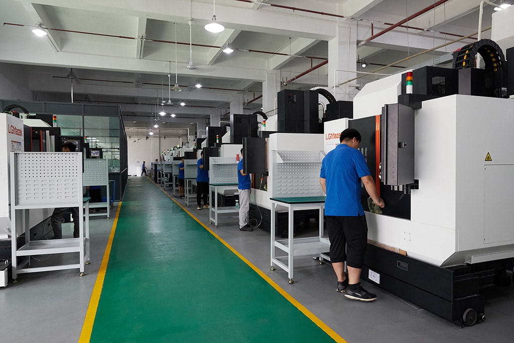

Not every tight callout earns its cost. Machining cost is nonlinear in tolerance: moving from ±0.1 mm to ±0.003 mm (milling) / ±0.002 mm (turning) can more than double the price, because the machine, the number of setups, the tooling, and the inspection all change at once. The question you should ask is whether the function actually demands the tight band, and many drawings carry bands the function never asked for.
The test is to work backward from the function. A bore that locates a bearing needs its position and roundness held tight. A clearance hole that a bolt passes through does not. A face that seals needs its flatness; a cosmetic face does not. If you cannot name the mating part that a tolerance protects, the tolerance is probably tighter than it needs to be.
The tell-tale signs of over-tolerancing show up on the print itself. Every dimension carries the same tight band, when a real drawing has a hierarchy — a few critical features tight and everything else relaxed. A ±0.003 mm (milling) / ±0.002 mm (turning) callout sits on a surface nobody touches. A position callout appears without a datum. These are the fingerprints of a tolerance copied from a template instead of derived from a fit.
A shop that flags these in the design-for-manufacturing review is saving you money, not being difficult. Relaxing a tolerance the function does not need is the cheapest cost reduction on the print — it happens before any metal is cut, and it costs nothing but a conversation.
Cost deep dive: CNC Precision Machining Cost in 2026: your Cost Model for the Drawing, Not the Rate Card
When does holding a tight tolerance actually fail?
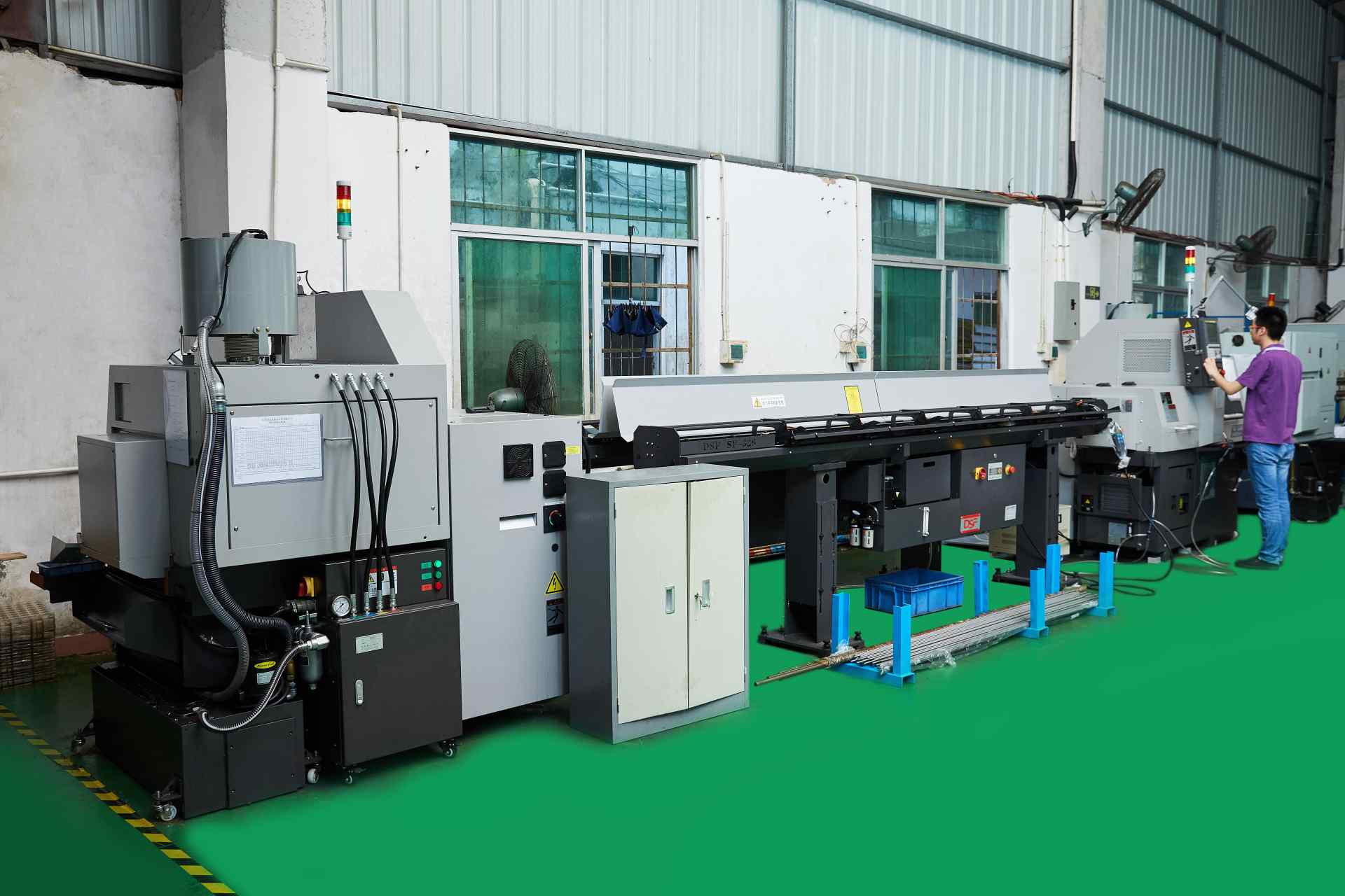
Holding a tolerance is a process-control problem, and it fails in predictable ways. Knowing the failure modes is how you separate a capable shop from a lucky one, because a lucky shop gets the first article right and the next thousand wrong.
- Thermal drift. The part is measured at the wrong temperature, or the material grows between the machine and the CMM. A shop without temperature control cannot honestly hold the tightest bands.
- Fixturing error. The part is clamped on a surface other than the datum, so every measurement is wrong in the same direction. This is the most common and most invisible error, because the part "measures fine" against the wrong reference.
- Tool wear. A cutting tool wears over the run and the dimension drifts with it. Without SPC and tool-wear compensation, the last part is not the same as the first.
- Material inconsistency. A mixed lot of stock machines differently, and the tolerance drifts with it. This is why incoming material is XRF-checked before it reaches a machine.
- The inspection gap. The shop verifies size but not form, or measures a profile callout with a caliper. The part passes and still does not fit.
The counter-question you should ask is simple: name the failure mode you watch for on my part. A shop that can answer is controlling the process. A shop that cannot is hoping, and hope is not a capability.
Industry deep dives: CNC precision machining for medical · CNC precision machining for semiconductor equipment · aerospace precision machining.
Process comparison deep dive: CNC precision machining vs 3D printing, die casting, and injection molding.
How do tolerance demands differ across industries?
The same ±0.003 mm (milling) / ±0.002 mm (turning) means different things in different industries, because the failure cost and the verification burden differ. The tolerance on the print is identical; what changes is how much proof must travel with the part.
- Automotive. Tolerances are medium-tight, but the emphasis is on repeatability and traceability across high volume. IATF 16949, PPAP documentation, and SPC charts are the working currency, because the fit has to hold over hundreds of thousands of parts, not dozens.
- Medical devices. Tolerances are often tight on small features, and the documentation burden is high — every dimension traceable to a record, because a failure is a patient rather than a warranty claim.
- Robotics and automation. The dominant callout is position between features across a housing, where a joint or an actuator mates. A mis-located bore pattern is the difference between a robot that moves and one that binds.
- E-bikes and consumer goods. Tolerances are looser but cost pressure is high. The shop's job is to hold the fit without over-engineering the price.
- Semiconductor and optics. The tightest bands live here — flatness and surface finish at the sub-micron level, where the temperature and vibration of the room decide the answer more than the machine tool.
The lesson for you: tell the shop which industry the part serves. The process discipline is the same, but the verification depth and the documentation are scaled to the failure cost, and a shop that does not know your industry cannot know how much proof to send.
The failure cost also shapes the tolerance hierarchy within a single print. An automotive part might carry one truly tight callout — the bore that locates a bearing — and a dozen relaxed ones, because that is where the money is. A medical part might spread the tightness more evenly, because several features each carry a safety function. Reading a drawing with the industry in mind tells you which callouts you will actually inspect at incoming, and those are the ones a shop must never let slip.
How do overseas markets treat tolerance and documentation differently?
The tolerance on the print is universal; how it is verified and documented varies by market. A buyer shipping into Europe, North America, Japan, or Australia should know the general differences, because they change what the inspection report must contain.
- Europe. Buyers commonly expect a full dimensional report with every shipment and reference to ISO standards — ISO 9001, ISO 2768, and the ISO 1 reference temperature. Documentation is formal and auditable.
- North America. GD&T is written to ASME Y14.5, so a shop must read both the ASME and the ISO dialects — the symbols mostly overlap, but some rules differ. PPAP-style documentation is standard for automotive.
- Japan. The emphasis is on process stability and cleanliness of the whole chain. Incoming material traceability and a consistent, demonstrated Cpk are table stakes, not extras.
- Australia and New Zealand. Volumes are smaller but the certification expectations track Europe, and importers lean on the dimensional report to clear incoming inspection at the dock.
The practical point for you: ask the shop which GD&T standard it reads — ASME Y14.5 or ISO GPS — because a position or profile callout can be interpreted differently under each. A shop that answers "both, and we confirm which one your drawing uses before quoting" is the one to trust with a print that crosses a border.
What should a buyer ask before trusting a tolerance claim?
Every tolerance claim can be tested with a handful of questions, and the answers are more revealing than the claim. Ask these of any shop — including this one.
- Which process will hold each tight callout, and why? The answer should name a machine and a method, not a slogan. A bearing seat needs grinding; a housing pocket needs milling.
- Can you show a CMM report or an SPC chart from a real part? Evidence is a number with a date and a batch attached, not a capability statement on a brochure.
- How do you establish my datums in fixturing and on the CMM? If the shop hesitates, it is measuring from whatever surface is convenient, and the datum order is the contract.
- Which GD&T standard do you read — ASME Y14.5 or ISO GPS? The answer tells you whether the shop can read the print the way your customer will.
- What happens when a dimension is out of tolerance? The right answer is "we flag it in the DFM review before cutting." The wrong answer is a silence that turns into scrap.
- Are the certificate numbers verifiable? A real ISO or IATF certificate has a number you can check with the registrar. Ask for it, then check it.
A shop that welcomes these questions is a shop that measures. A shop that deflects them is a shop that hopes. The difference is the whole point of this page.
China sourcing deep dive: what to verify before you pay a Chinese machining supplier.
Guides
- Aerospace CNC Precision Machining: Materials, Documentation, and the Tolerance Expectations That Matter
- China CNC Precision Machining Sourcing: What to Verify Before You Pay
- Aluminum vs Stainless for CNC Precision Machining: The Decision Table for Tolerance, Weight, and Corrosion
- CNC Precision Machining vs Alternatives: Choosing the Material–Process Pair That Wins Your Part
- CNC Precision Machining Cost in 2026: A Buyer’s Cost Model for the Drawing, Not the Rate Card
- Aluminum CNC Precision Machining: Alloys, Stability, and the Tolerance Decisions That Matter
- CNC Precision Machining for Medical: Tolerances, Materials, and the Documentation a Device Maker Needs
- CNC Precision Machining for Semiconductor Equipment: Tolerances, Cleanliness, and the Proof a Tool Builder Needs
Send the drawing, and we will read the fit first.
Email your STEP or IGES model and toleranced 2D drawing to [email protected] or call +86 13126536955 for a design-for-manufacturing review and quote.
Frequently Asked Questions
What is the difference between a ± dimension and a GD&T tolerance?
In short, A ± dimension controls only the size between two points, while a GD&T callout controls form, orientation, and location against a datum reference frame. GD&T describes how a feature may deviate and still function in an assembly, which is why it is the language of fit.
What is a datum, and why does it come first?
In short, A datum is a reference surface or axis from which other features are measured, and it must be established before any tolerance means anything. Without datums, two parts machined identically can still fail to assemble because they were never located from the same reference.
What is true position, and how does it differ from a ± tolerance?
In short, True position uses a cylindrical tolerance zone around the theoretically exact location of a feature, which is about 57% larger than the square zone a ± tolerance describes. This lets a hole drift further from nominal without rejecting a functionally good part.
How does an assembly tolerance shrink the tolerance on each part?
Every part in a chain adds its own variation, so the allowed deviation on each part must be smaller than the total the assembly can accept. A fit clearance is divided among the mating parts, and each part carries only its allocated share.
What tolerance can CNC precision machining hold?
In short, ±0.003 mm on CNC milling, ±0.002 mm on CNC turning, and ±0.002 mm for precision grinding. Critical dimensions are verified on Hexagon CMMs, with process capability Ppk ≥ 1.67 at the initial study on key characteristics and a recorded Cpk of 1.851 (one characteristic on one part, not a blanket capability claim) on a representative length.
How do you verify a GD&T callout before a part ships?
Form, orientation, location, and profile callouts are measured on Hexagon CMMs and vision machines against the CAD model, and the results are reported. You receive a dimensional report rather than a pass/fail note.
What should I send to get a quote?
Send your 3D STEP or IGES model plus a 2D drawing with the GD&T callouts to [email protected]. We return a design-for-manufacturing review and a quote, usually within one business day.
What is the difference between ASME Y14.5 and ISO GPS?
In short, Both are GD&T dialects that use similar symbols, but they differ in how some callouts are interpreted. ASME Y14.5 is the North American standard; ISO GPS is the international system.
What surface finish (Ra) do I need on a sealing face?
In short, A sealing face usually needs Ra 0.8 µm or finer, because a coarser surface leaves leak paths between the peaks. Bearing bores and sliding surfaces sit in the same range.
What does ISO 2768-m on my drawing actually mean?
In short, It sets a default tolerance for any dimension without its own callout. Under ISO 2768-m, a 50 mm dimension carries ±0.3 mm automatically.
What happens if the shop cannot hold a tolerance on my print?
In short, A build-to-print shop tells you during the design-for-manufacturing review, before metal is cut. You get a note on which feature is not achievable as drawn and a suggestion for what would make it machinable, not a promise that quietly turns into scrap.
Why does a tighter tolerance cost so much more?
In short, Cost is nonlinear in tolerance. Tighter bands change the machine, the number of setups, the tooling, and the inspection method — a feature at ±0.003 mm (milling) / ±0.002 mm (turning) may need grinding or a CMM pass that a ±0.1 mm feature never touches.
Do you use MIL-STD-105E or ANSI/ASQ Z1.4 sampling inspection?
In short, MIL-STD-105E is the U.S. military sampling inspection standard published in 1989; it specifies acceptable quality limit (AQL) sampling plans for lot-by-lot inspection.
Standards referenced on this page
- IATF 16949:2016 — Automotive quality management system standard
- ASTM B209/B209M-21 — Standard Specification for Aluminum-Alloy Sheet and Plate
- ASTM E8/E8M-21 — Standard Test Methods for Tension Testing of Metallic Materials