
CNC Precision Machining for Semiconductor Equipment: Tolerances, Cleanliness, and the Proof a Tool Builder Needs
CNC Precision Machining for Semiconductor Equipment: Tolerances, Cleanliness, and the Proof a Tool Builder Needs — Semiconductor equipment is precision machinery with a contamination problem bolted to it. Tolerances: ±0.003 mm milling, ±0.002 mm turning — ISO 9001 / IATF 16949 verified.
Semiconductor equipment is precision machinery with a contamination problem bolted to it. The tool that processes a wafer is judged not by whether its machined parts match a drawing, but by whether those parts assemble into a stage that moves true, a chamber that seals, and a handling system that never sheds a burr or a particle onto a wafer. That shifts what a machine shop has to prove. A bracket or chamber plate for a lithography, etch, deposition, or inspection tool is still machined to microns, but the flatness, the edge condition, and the material record carry functional weight they do not carry in ordinary hardware. This guide is written for the engineer or sourcing lead who buys those parts: which machined components a semiconductor tool actually needs, what tolerance and surface requirements are real, where the "clean" claims need evidence rather than adjectives, and how to qualify a CNC shop before your first drawing crosses the Pacific.

Which machined parts in semiconductor equipment actually demand precision?
Not every machined component in a semiconductor tool carries the same risk, and if you treat them alike, you over-specify the easy parts and under-specify the hard ones. In practice, the metal and plastic parts a CNC shop supplies to semiconductor equipment OEMs and their sub-suppliers fall into a few families, each with its own tolerance logic:
- Motion-stage structural parts — the carriages, baseplates, brackets, and motor-mount housings under a wafer or reticle stage. These parts carry the flatness, parallelism, and hole-position callouts that decide whether a linear stage moves straight and repeats. A mounting face that is flat to a few microns is what lets a stage assemble without shimming; a hole pattern that drifts puts the encoder, the motor, or the guide rail out of alignment before the stage ever moves.
- Chamber and vacuum-system hardware — chamber walls, lids, flanges, and gas-panel frames where the part carries sealing surfaces and feedthrough locations. The sealing face is ground and flatness-controlled; the flange bolt circle is true-positioned to the port it surrounds. These parts are often large relative to their tolerances, which is exactly why they are hard: holding a sealing surface flat across a wide plate is a fixturing and stress-management problem, not just a spindle problem.
- Wafer-handling and transfer components — end-effector brackets, gripper frames, lift-pin guides, and the non-contact structural parts that move wafers between stations. The constraint here is edge condition and cleanliness as much as dimension: a burr on a handling component is a particle generator aimed at the wafer, and an edge that sheds is a yield risk even when every dimension is correct.
- Measurement and inspection fixtures — the brackets and fixtures that hold a sensor, a camera, or a probe in a metrology tool, where the position of the sensor relative to the datum is the entire function of the part.
- Fluid, gas, and thermal hardware — manifold blocks, cooling-plate frames, and line brackets. Some of these carry a sealing function; others simply hold a line or a plate in place. The honest specification separates the ones that must seal or meter flow from the ones that only position hardware.
One boundary is worth stating plainly: the most sensitive semiconductor components — electrostatic chucks, direct wafer-contact surfaces, ceramic and quartz parts — are a different supply class, usually owned by ceramic specialists and the tool builder itself. The scope of a CNC precision machining supplier is the structural and motion hardware around those components. A shop that implies it will make the chuck is overstating its role; the useful question is whether it can make the metal structure the chuck mounts into, hold the flatness the interface demands, and document the lot so the assembly stays traceable.
Why flatness and parallelism matter more than a size tolerance in tool hardware?
A buyer moving from general precision work into semiconductor equipment meets the same drawing vocabulary — position, profile, flatness, parallelism — but the emphasis shifts. On a consumer or industrial part, the critical callout is often a bore or a true position. On semiconductor equipment, the load-bearing callouts are usually form and orientation: flatness on a mounting face, parallelism between two faces, and position across a pattern of holes that must line up with a rail, an encoder, or a mating chamber flange.
The reason is that a semiconductor tool is an assembly of stacked precision surfaces. A stage baseplate, its guide-rail mounting faces, the carriage, and the chuck platform all stack on top of each other. If each face is out of flat by a few microns, the errors accumulate at the top of the stack, where the wafer sits, and a stack that has absorbed 20 microns of tilt cannot be fixed by software. Size tolerances are part of the story, but they do not describe a face that rocks, a mating surface that is crowned, or a flange that sits down on three points instead of its whole face. Only geometric tolerances describe those, and only a CMM or a form-measuring instrument can verify them.
Parallelism deserves its own sentence, because it is the callout that most often surprises a shop new to this work. Two faces can each be perfectly flat and still be non-parallel to each other by an angle that ruins the assembly. A stage that must move in X while staying square to Y depends on the parallelism between its guide faces, and parallelism is measured from a datum face, which means the datum scheme on the drawing is not paperwork. It is the instruction for how the part is fixtured and how the CMM aligns it. Ask a candidate shop how it establishes your datums on the machine and on the CMM; the answer separates a shop that reads the drawing from one that measures what is convenient.
What tolerances can you hold on semiconductor equipment parts?
The capability numbers for this work are the same numbers a serious precision shop holds on any demanding part, because the machines and the metrology do not change with the industry — the discipline does. On the shop floor that backs this site:
- Milling, turning, and mill-turn hold ±0.003 mm (milling) / ±0.002 mm (turning) on critical features, which covers bores, bosses, sealing faces, and true-position hole patterns across the part families above.
- Precision grinding reaches ±0.002 mm, which is where flat sealing faces, chuck seating surfaces, and close-tolerance OD/ID work are finished.
- Process capability is tracked at Ppk ≥ 1.67 at the initial study on key characteristics and Cpk ≥ 1.33 on general characteristics. Capability is reported per characteristic: every report names the feature, its tolerance band, the sample size, the sigma method, and the study window. Under SPC — a recorded Cpk of 1.851 (one characteristic on one part, not a blanket capability claim) on a representative length shows the process is centered and inside the band, not scraping past it. The distinction matters to a tool builder: a prototype that passes inspection is a sample; a process that runs at Ppk ≥ 1.67 initial is a production capability.
Read the tolerance band before you read the index. Cpk is a ratio of the tolerance band to the process spread, not an absolute measure of accuracy. The figure above was recorded on a length characteristic with a 0.4 mm band (76.1–76.5 mm) — wide by design. Hold the same process spread against a ±0.005 mm feature and it fails outright. Ask for the band, the subgroup count and the sampling window on every capability number a supplier quotes.
Which process holds which band — and where grinding becomes necessary — is laid out in detail on the CNC precision machining services overview.
What changes in semiconductor work is not the tolerance itself but how tightly the shop guards the features that carry the tool's function. A stage mounting face and a cosmetic outer surface on the same part should never share a band; the tight callouts are allocated to the faces that locate, seal, or move, and the rest of the part runs at commercial tolerance. That allocation is a design decision the drawing should already make, and a supplier's design-for-manufacturing review should confirm it before any metal is cut, flagging features that are tighter than the function needs as well as features that cannot be held as drawn.
Which materials and surface conditions fit a clean-process environment?
Material choice on semiconductor equipment hardware is driven by stability, corrosion resistance, and cleanability, and by the finish the part must survive. The everyday workhorses a machine shop actually cuts for this industry are narrower than the full material list:
- Aluminum 6061 and 7075 — the default for stage plates, brackets, chamber walls, and cooling hardware. 6061 is the stable, predictable choice for most structural and motion parts; 7075 carries higher strength where the part sees load. Both machine cleanly and hold the ±0.003 mm (milling) / ±0.002 mm (turning) band without surprises, which is what makes aluminum the backbone of semiconductor tool hardware. Hardcoat anodize (Type III) is commonly specified on aluminum for wear and corrosion resistance, and because hardcoat grows the dimension, the coating allowance must be machined in, not discovered after the fact.
- Stainless 303, 304, 316, and 17-4PH — for wetted, corrosion-critical, or higher-strength hardware. 316/316L is the choice where corrosion resistance and cleanability dominate; 17-4PH is specified where the part must be strong and stable, machined annealed and aged to a stated condition. Stainless is work-hardening, so the shop quotes realistic cycles rather than pretending it cuts like aluminum.
- Engineering plastics — PEEK, POM/Delrin, and similar — for insulating, lightweight, or wear components where a metal part would conduct, corrode, or shed. Plastics move with temperature and moisture, so their tolerances are managed differently from metal; a shop that machines them daily treats them as their own material class, not as "soft metal."
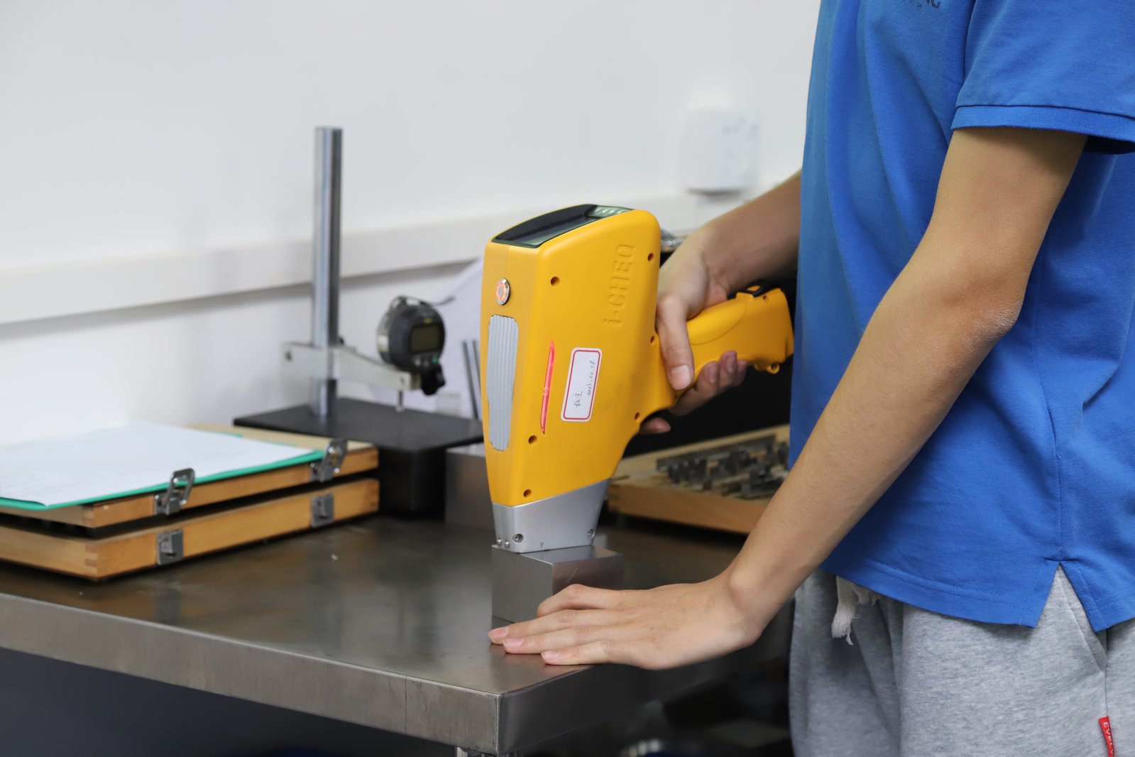
Material identity is the part of the specification no dimensional report can verify, which is why incoming lots are checked by XRF against the mill certificate before the stock reaches a spindle. A substituted alloy — a 6061 lot quietly replaced by a look-alike, or a 316L bar that is not what the cert claims — passes every dimension and fails in the clean process environment, where corrosion or outgassing becomes a tool problem. Lock the grade on the drawing, and make the supplier prove the lot matches the cert.
What does "clean" require, and what should a buyer verify instead of assuming?
"Clean" is the most abused word in semiconductor supply discussions, and it deserves precision. A machined part leaves the spindle with coolant, oil, chips, and burrs on it; a burr or an embedded particle that breaks loose inside a tool is a yield event. So the real requirement has three concrete parts:
- Burr-free edges and features. Every edge, hole, groove, and thread that could shed a burr is deburred and edge-broken, then checked. Burr-free is a written requirement with a verification step, not an intention — ask how edges are deburred and how the result is confirmed.
- A cleaning process matched to the material. Coolant and oil are removed with a documented cleaning step appropriate to the metal or plastic, so nothing is left behind and nothing is embedded. A blind hole that traps coolant is a contamination trap; the shop should be able to say how it cleans and confirms the parts it ships.
- Protective handling and packaging. A clean part that is handled bare-handed, packed against metal, or shipped in a dusty carton is not clean on arrival. Packaging that separates, cushions, and protects the machined surfaces is part of the deliverable.
Here is the honest boundary you should hold a shop to: if your program demands a stated cleanliness class, a particle-count certificate, or an outgassing test, ask for it in writing and confirm the shop can meet and document that specific requirement before you release the drawing. A supplier that says "we are clean" without naming the standard, the test, or the certificate is asking you to accept the risk on its behalf. The mature answer is a scope conversation: the shop states what its cleaning and packaging can prove, you state what your spec requires, and the gap — if any — is resolved before the part exists rather than after a contamination event. Claims about cleanliness should always be treated as claims until the evidence ships with the parts.
What documentation should ship with semiconductor equipment parts?
Semiconductor equipment buyers do not qualify a shop to make one bracket; they qualify a supplier whose documentation makes the part usable in a tool qualification. The record set a serious supplier ships with these parts — and what your incoming inspection should expect — is the same discipline covered on the quality assurance page, where the CMMs, SPC charts, and first-article practice behind this site are described. That set includes:
- Material certificates with the alloy, grade, condition, and heat or lot identity, backed by the XRF verification record from receiving. For 316/316L and for aged 17-4PH, this chain is the part of the file that proves the chemistry.
- Dimensional reports from a named coordinate measuring machine showing measured values against the drawing — position, profile, form, and orientation against your datum scheme — rather than a pass/fail note. The report should state the measurement temperature, because a flatness number measured at an uncontrolled temperature is a number without context.
- First-article documentation on the first part of a new drawing or revision, covering every characteristic that carries function. This is where a misinterpreted datum, a coating-growth miscalculation, or a tolerance that cannot be held surfaces cheaply — before a production run repeats it.
- SPC evidence on key characteristics during production, showing the process stayed inside the tolerance band rather than being sorted after the fact.
- Special-process records where the drawing calls for them — hardcoat anodize, passivation, heat treatment — from the vendor that performed the step, tied to the same lot.
One rule makes the whole set useful: every document must describe the same part, same revision, same lot. A file that does not tie together is how a wrong lot slips through an incoming inspection that is checking the paperwork, not the metal.
How should you qualify a CNC shop before sending semiconductor work?
Semiconductor hardware rewards verification more than almost any other machining purchase, because the failure cost is a contaminated tool or a stalled qualification, not a scrapped part. A practical screen for a candidate shop:
- Material control at receiving. Ask what happens when a bar of 6061 or 316L arrives. The answer should name an XRF check against the mill certificate, with the lot locked to the job, not an adjective like "careful."
- Datum and tolerance reading. Send a sample drawing with a flatness and parallelism callout and ask how the shop will fixture it and measure it. The answer should name the datum scheme and the CMM — this is the single fastest test of whether the shop reads geometric tolerances as instructions.
- Metrology named, not implied. The quality answer should mention coordinate measuring machines by make, plus the form and roughness instruments behind the report. A shop that can name its CMMs can usually show you a sample report that names them too.
- A sample dimensional report and SPC chart. Ask to see a real one from a recent tight-tolerance job. It should show measured values against the drawing and a capability picture, not a stamp.
- Burr and cleaning discipline. Ask how edges are deburred and verified, and what the cleaning and packaging steps are. The answers should name processes, not intentions, and if your spec demands a cleanliness certificate, get the shop's written confirmation before you release the drawing.
- Traceability across the file. Ask how material certs, XRF records, dimensional reports, and first-article documents are linked by lot and revision. The supplier should be able to show the chain, not claim it exists.
- Change control. Ask how drawing revisions are managed and whether you will be told before any process change — tooling, material source, or finishing vendor — touches a released part. Silent changes are how a qualified part stops being the part you qualified.
Send these questions by email before you send geometry. A shop that answers with instrument names, document names, and certificate numbers is running the system your tool depends on; one that answers with assurances is asking you to carry the risk. The same discipline that satisfies this screen is what the shop will apply to your parts, which is why the screen is worth running before the first RFQ.
What drives cost and lead time on semiconductor equipment parts?
Four factors move the price and schedule of machined semiconductor hardware more than anything else, and a buyer who reads them keeps both realistic:
- The material. Certified aluminum with full traceability costs more than generic stock; 316/316L and 17-4PH cost more than 303; hardcoat anodize adds a process step with its own dimensional control. If the application can use 6061, it should, and if it needs 316L or 17-4PH, that price is the honest price.
- The number of tight features. Each ±0.003 mm (milling) / ±0.002 mm (turning) callout and each flatness or parallelism band adds machining time and inspection. Protecting the few faces that carry the tool's function and leaving the rest on the general block is the largest single lever on cost.
- Large geometry relative to tolerance. A stage plate or chamber flange that must be flat across a wide area is a fixturing and stress-management job. The same callout on a small bracket is trivial; on a 600 mm plate it is the whole job.
- Documentation and special processes. Material certificates, XRF records, first-article reports, SPC, hardcoat anodize, and passivation are labor, and they are charged as such. A supplier quoting them as line items is being honest; one absorbing them silently is either cutting corners or hiding them in the margin.
Lead time follows the same shape: material availability and certification, the machine time the geometry demands, and the inspection scope. Because tool development runs on iteration, order quantities are often small — this shop runs minimum order quantity of one, with prototypes on the same machines and tolerances as production, and lead times of roughly 3, 7, or 30 days depending on complexity. That matters in semiconductor work, where a design revision resets part of the qualification clock and the ability to order a handful of corrected parts without committing to a production run is the difference between iterating and stalling.
What this shop actually runs
If you ask for capability evidence, you deserve a specific answer. This facility operates 100+ CNC machines across 6,800 m2 in Dongguan, China, staffed by 100+ people. The machines, listed by category:
- 5-axis machining centres (10+) - Mazak VARIAXIS I-600 (510/910/510 mm travel, 12,000 rpm, 22 kW, 71.6 N·m, 30-tool BT40) and Mazak INTEGREX I-250H S (B-axis 0.0001°, 24 kW, 124 N·m, 38-tool HSK-A63). Intended for compound-angle parts, single-setup multi-face prismatic work, and aerospace fittings where datum transfer loss is unacceptable.
- 3-axis / 4-axis machining centres (50+) - Brother SPEEDIO S500Z2N / S700Z2N (10,000 rpm, 14/21-tool ATC, 0.7 s tool-to-tool, Z-axis 2.2 G) and Mazak VCE-430A L / VCE-570C L (10,000 rpm, 118 N·m, 24-tool ATC). Intended for prismatic parts, plates, brackets, housings.
- Swiss-type turning centres (10+) - Citizen Cincom A20-3F7 (Φ20 mm, 10,000 rpm), TSUGAMI B0206-III / B0205-III (Φ20 mm, 0.1 µm), STAR SR-32JII / SR-32J Type N (Φ32 mm, 8,000 rpm). Intended for long, slender rotational parts at ±0.002 mm.
- CNC turning centres (20+) - HEADMAN T70M/1250 (720 mm swing, 117 mm bore, 3,000 rpm, BMT75 12-station turret). Intended for shafts, bushings, flanges up to ±0.002 mm.
- Wire EDM (5+) - Sodick AQ535L (550/350/300 mm travel, ±20° taper, 800 kg workpiece). Intended for hardened tool steel, internal splines, sharp internal corners that milling cannot reach.
- Inspection: Hexagon CMM + 20+ gauges - Hexagon CMM for coordinate measurement, plus vision system, profilometer, hardness tester, coating thickness gauge, XRF for material verification. The 10:1 rule (gauge 10x more accurate than the band) is applied to every feature.
- Machine highlights - VARIAXIS I-600: one-setup multi-face 5-axis + MAZA-CHECK auto-calibration; INTEGREX I-250H S: DONE-IN-ONE mill-turn, B-axis 0.0001° + Ai thermal shield; SPEEDIO S500Z2N / S700Z2N: Z-axis 2.2 G + 0.7 s ATC; Swiss-type: guide-bush switchable + 0.1 µm resolution.
Tolerance bands: ±0.003 mm milled, ±0.002 mm turned, ±0.002 mm ground or wire-cut. Capability indices: Ppk >= 1.67 at the initial study; Cpk >= 1.33 ongoing in production.
Certifications: ISO 9001:2015 (116024/A/0001/UK/En) · IATF 16949:2016 (131941/A/0001/SM/En, design clause 8.3 excluded) · ISO 14001:2015 (116024/B/0001/UK/En), held by Dongguan Zhuohang Ltd (USCC 91441900MA4UWT6X39, since 2005).
Service area: we supply Austria, Belgium, the Czech Republic, Denmark, France, Germany, Greece, Hungary, Ireland, Italy, the Netherlands, Spain, Sweden and the United Kingdom in Europe; Brazil, Canada, Mexico and the United States in the Americas; China, Israel, Japan, Singapore and Sri Lanka in Asia; Australia and New Zealand in Oceania; and South Africa in Africa, with worldwide delivery from China.
Contact: Felipe Iglesias, [email protected], +86 13126536955.
Send the drawing with the datums, the cleanliness requirement, and the finish, and get a straight answer on all three.
Email your STEP or IGES model and toleranced 2D drawing to [email protected] or call +86 13126536955. We return a design-for-manufacturing review that flags the features driving cost and risk, the tolerance we can hold, and — where your spec demands proof — exactly what documentation and cleanliness evidence we can ship with the parts.
Frequently Asked Questions
What tolerances can you hold on semiconductor equipment parts?
In short, Milling, turning, and mill-turn hold ±0.003 mm (milling) / ±0.002 mm (turning) on critical features; precision grinding reaches ±0.002 mm for sealing and seating surfaces. Process capability is tracked at Ppk ≥ 1.67 at the initial study on key characteristics and Cpk ≥ 1.33 on general characteristics.
Which materials do you machine for semiconductor equipment hardware?
In short, Aluminum 6061 and 7075 (with hardcoat anodize available), stainless 303, 304, 316, and 17-4PH, and engineering plastics such as PEEK and POM/Delrin. Every incoming lot is verified by XRF against its mill certificate before machining, and the grade on the drawing is the grade that runs.
Can you hold flatness and parallelism across a large stage plate or chamber flange?
In short, Yes — flat and parallel faces are verified with form measurement and CMM against your datum scheme, with fixturing and stress management planned for parts wide relative to their tolerance. Send the flatness and parallelism callouts with the datums and we hold the part to them, quoting the features the drawing actually demands.
Do you provide cleanliness documentation or particle certificates?
In short, Burr-free edges, material-matched cleaning, and protective packaging are part of every order. If your program requires a specific cleanliness class, particle-count certificate, or outgassing test, we confirm in writing what we can meet and document before you release the drawing — the gap is resolved up front, not discovered after a contamination event.
What documentation ships with a semiconductor equipment order?
In short, Material certificates backed by XRF verification records, dimensional reports from named CMMs measured at a stated temperature, first-article documentation, SPC evidence on key characteristics, and special-process certificates — hardcoat anodize, passivation, heat treatment — all linked to the same lot and revision.
Can you machine a single prototype before production?
Yes — MOQ is one piece, and prototypes run on the same machines and tolerances as production, with first-article documentation on every revision. Tool-development iterations can be ordered in small lots without committing to a production run.
Which certifications does the shop hold?
ISO 9001:2015, IATF 16949:2016, and ISO 14001:2015 — with the IATF scope excluding product design under Clause 8.3, as a build-to-print manufacturer. Quality documentation travels with every order on request.
Standards referenced on this page
- ASTM B211/B211M-19 — Standard Specification for Aluminum-Alloy Rolled or Cold Finished Bar, Rod, and Wire
- ASTM A276/A276M-17 — Standard Specification for Stainless Steel Bars and Shapes
- ISO 9001 — Quality management systems — Requirements