
Most tolerance problems on precision machined parts are not machining problems; they are drawing problems. A drawing that instructs clearly machines smoothly, and a drawing that leaves its intent scattered or ambiguous produces first-article surprises, mid-route questions and inspection arguments. The difference between the two is drafting discipline: a general tolerance that sets a sensible floor, feature-level callouts that are few and justified, finishes named by function, and the tolerance and finish of each critical feature written together. This guide covers that discipline, so a drawing arrives at the shop already able to be held and at the inspector already able to be verified.
Why do some drawings machine smoothly and others fight at the first article?
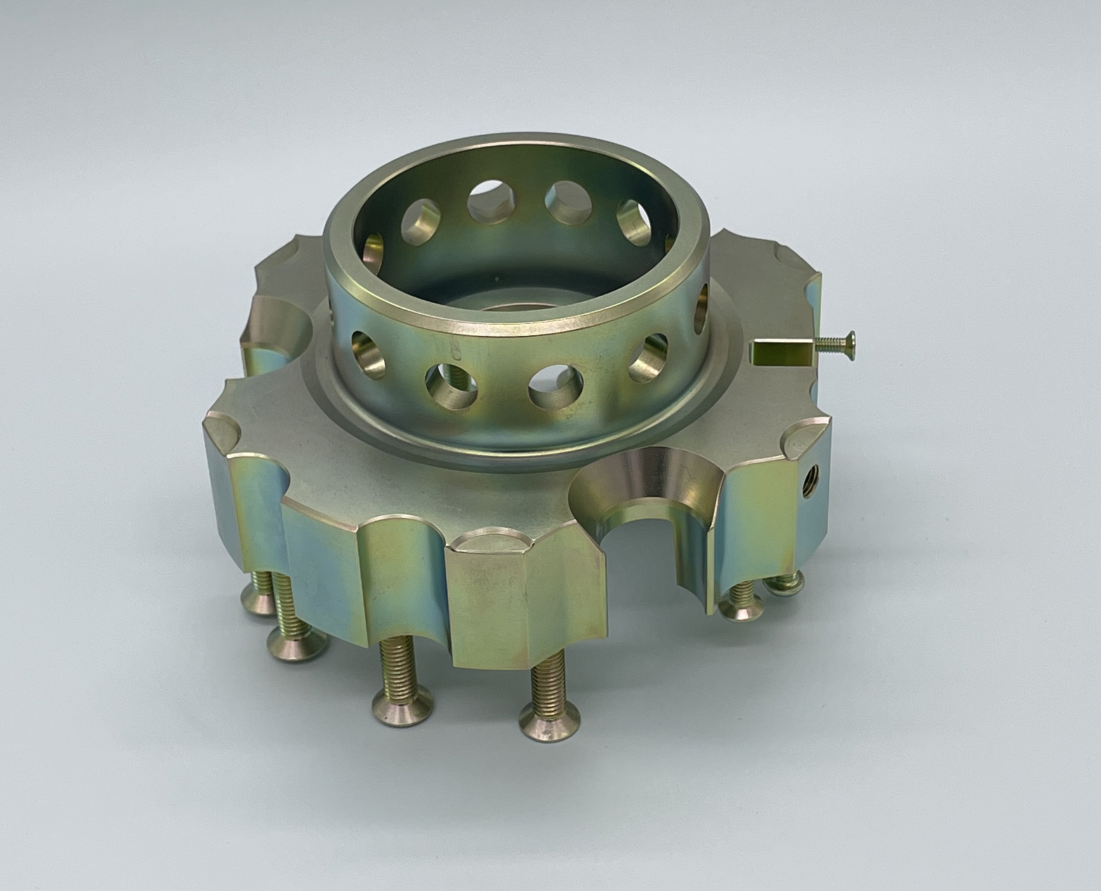
A drawing is a set of instructions, and the quality of the machining follows the quality of the instructions. A clear drawing tells the shop which features are critical and which are not, what tolerance each critical feature carries, and what finish each surface must reach — all in a form the programmer, the machinist and the inspector read the same way. An unclear drawing leaves those questions open, and every open question is answered differently by the people who touch the part: the programmer assumes one thing, the machinist another, and the inspector discovers the difference at the first article.
The cost of drawing ambiguity is paid in first-article cycles. A first article that fails because the drawing was unclear is not a process failure; it is a specification failure, and it costs exactly the same as a machining failure — the part, the review, the re-run — without improving the process at all. The drawings that machine smoothly are the ones whose authors have done the thinking in advance: which features matter, what each needs, and what the part can be allowed to ignore. The discipline is not bureaucratic; it is the difference between instructing a shop and negotiating with it.
What should the general tolerance block contain?
The general tolerance block is the floor the whole part runs at, and it deserves the same thought as the feature-level callouts above it. It should name the default band for every dimension the drawing does not call out individually — typically a machined standard such as ±0.1 mm or ±0.05 mm, or the industry block your sector uses — and it should state the default conditions for edges, radii and surface finish that the drawing does not specify elsewhere. The general tolerance sets the cost floor of the entire part, because every dimension not individually called out runs at it.
The most common general-tolerance error is setting the floor tighter than the part needs. A general tolerance of ±0.05 mm on a bracket whose function could accept ±0.2 mm is a floor that inflates the cost of every dimension on the drawing without protecting anything, because none of the dimensions needed the tighter band. The general tolerance should be as loose as the function honestly allows, so the precision budget is spent only on the features that are called out individually. A drawing whose floor is honest is a drawing whose premium is visible where it is spent, and that is the drawing a shop can price lean.
Which features deserve their own tolerance callout?
Feature-level callouts exist to protect function, and the features that deserve them are the ones whose failure breaks the assembly. A fit between two mating parts carries its own band because the assembly depends on the clearance; a bore that carries a bearing is called out because the bearing rides on it; a face that a seal runs against is called out because the seal depends on its flatness and finish; and the datum that locates everything else is called out because every other measurement hangs off it. Each of these is a feature the drawing names individually because the general tolerance could not protect it.
The features that do not deserve callouts are the ones the general tolerance protects fine. A dimension that nothing mates with, a position that nothing depends on, a face whose finish is invisible to the function — each is a candidate for the block, and moving it back to the block is where precision budgets get recovered. The rule of thumb is simple: if a feature can run at the general tolerance without changing the assembly, it should run there. The discipline is not to avoid callouts; it is to spend them where the assembly actually needs them, and to let the DFM review challenge every callout that cannot name a function it protects.
The drafting hierarchy is worth making explicit on the drawing itself, because a shop reads the drawing in layers. The general tolerance is read first, establishing the floor for everything. The feature-level callouts are read second, naming the exceptions that carry function. The datum structure is read third, telling the shop and the inspector where each measurement starts. When the layers agree — the exceptions sit above an honest floor, and every exception has a datum to anchor it — the drawing reads the same way to the programmer, the machinist and the inspector. Drawings that fight at the first article are usually drawings whose layers disagree: a tight callout with no datum, a finish with no process, an exception sitting on a floor that was never honest. Layering the drawing is not decoration; it is how a specification becomes readable.
How tight should feature callouts go before grinding?

The band that cutting can hold is the boundary every feature callout has to respect. Machining holds fit and alignment features to ±0.003 mm (milling) / ±0.002 mm (turning), with capability of Cpk 1.67 or higher on key characteristics and Cpk ≥ 1.33 on general characteristics. Capability is reported per characteristic: every report names the feature, its tolerance band, the sample size, the sigma method, and the study window and features that genuinely need better are ground to ±0.002 mm. A callout inside the machining band can be produced and measured on the cutting cell; a callout below it needs the grinding cell, and the drawing should say so, because a tight number without a process note is a number the shop must interpret. The quote prices the process the callout implies, and the interpretation decides the price.
Writing the process into the drawing — "this journal is ground" — removes the interpretation entirely. It tells the shop which cell the feature belongs to, it tells the inspector what the report should carry, and it tells the buyer what the feature will cost before the quote arrives. A drawing that pairs its tightest callouts with their process is a drawing the shop can route without asking; one that leaves the process unnamed is a drawing that generates a question at the quote and possibly a surprise at the first article. Precision drawings are cheaper when they name their own processes, because naming a process is cheaper than discovering it.
How should surface finish be specified by function?
A finish callout should describe the surface's job, not the shop's hope. A machined finish around Ra 3.2 µm is what normal cutting passes leave, and for the general envelope — faces nothing seals against, nothing bears on, nothing is measured from — it is entirely adequate. Ra 1.6 µm belongs on functional and sealing faces, where a controlled surface is part of the part's job. Ra 0.8 µm and below belongs on bearing and sealing surfaces where the finish is produced by grinding or polishing, which are the processes that deliver those bands. Naming the finish by function tells the shop which pass to run and the inspector which faces to read.
The functional finish discipline also prevents the classic waste: one blanket Ra across the whole drawing. A single tight Ra forces the shop to polish faces nothing needs, because the drawing gave no way to distinguish the sealing face from the cosmetic one. Finish by function does the opposite: it spends the fine finishes on the faces that seal and bear, and leaves the general envelope at the machined standard. The drawing whose finishes are named by function is the drawing whose finishing cost is proportional to its finishing needs, which is the only proportion that makes sense.
Why do the tolerance and the finish belong on the same line?
On a machined feature the tolerance and the finish are produced together, which is why they belong on the same line of the drawing. The finishing pass that brings a diameter to its final band is the same pass that refines its surface; a grinding operation that holds a journal to ±0.002 mm also delivers the fine finish the bearing needs; and a surface that is polished without holding its size is a surface the shop cannot measure against anything. Writing the two together tells the shop to produce them as one requirement and tells the inspector to verify them in one reading.
The pairing also prevents the most common first-article mismatch: a dimension that is held but a surface that fails, or a surface that is polished while a dimension drifts. When the drawing says a sealing face is Ra 0.8 µm at its size band, the shop plans one pass that delivers both and measures both from the same setup. When the finish is buried in a general note and the size is called out alone, the pass that holds the size may leave the wrong surface, and the discovery happens at the first article. A drawing whose tolerance and finish travel together is a drawing whose features are specified whole, and whole specifications are the only ones a shop can be held to.
How do I check that my callouts are holdable before the quote?
The check that keeps callouts honest is the design-for-manufacturing review, run before the price is committed. For every feature-level callout, ask three questions: can the cell hold it, can the instrument measure it, and does the finish have a home process? A callout that survives all three is holdable and can be priced and scheduled with confidence. A callout that fails any of them — a band the machine cannot reach without grinding, a finish on a surface no instrument can read, a position with no datum to anchor it — is a callout that will fail at the first article, and the review is where it is cheapest to change.
The review should also test the drawing as a whole rather than feature by feature. Do the tight callouts share a small number of datums so the inspection runs in few frames? Do the finishes follow the functions so the finishing cost is proportional? Does the general tolerance sit at the honest floor so the precision budget is visible where it is spent? A drawing that passes the whole review is a drawing the shop can execute, the inspector can prove and you can price without contingency. The quality page on this site explains how callouts are measured and reported, and the parts guide shows how features carry their tolerances. A precision drawing written with an honest general tolerance, few justified feature callouts, finishes named by function and tolerance-finish pairs that travel together is a drawing whose promises are real before the first chip is cut.
The discipline pays its second dividend on revision and repeat. When a precision part is revised, the layers of the drawing make the change legible: a dimension moved in the feature layer leaves the floor and the datum story intact, so the revision's cost is contained to the feature it touched. When the part repeats, the drawing's clarity means the shop re-programs with confidence and the inspection re-runs without re-deriving the intent. A drawing that was written with drafting discipline is not only easier to hold the first time; it is easier to change and easier to repeat, which is where most of a precision part's lifetime cost actually sits. The drawings that cost the least over their lives are the ones whose authors wrote them to be read twice — once at the first article and once at every reorder.
What this shop actually runs
If you ask for capability evidence, you deserve a specific answer. This facility operates 100+ CNC machines across 6,800 m2 in Dongguan, China, staffed by 100+ people. The machines, listed by category:
- 5-axis machining centres (10+) - Mazak VARIAXIS I-600 (510/910/510 mm travel, 12,000 rpm, 22 kW, 71.6 N·m, 30-tool BT40) and Mazak INTEGREX I-250H S (B-axis 0.0001°, 24 kW, 124 N·m, 38-tool HSK-A63). Intended for compound-angle parts, single-setup multi-face prismatic work, and aerospace fittings where datum transfer loss is unacceptable.
- 3-axis / 4-axis machining centres (50+) - Brother SPEEDIO S500Z2N / S700Z2N (10,000 rpm, 14/21-tool ATC, 0.7 s tool-to-tool, Z-axis 2.2 G) and Mazak VCE-430A L / VCE-570C L (10,000 rpm, 118 N·m, 24-tool ATC). Intended for prismatic parts, plates, brackets, housings.
- Swiss-type turning centres (10+) - Citizen Cincom A20-3F7 (Φ20 mm, 10,000 rpm), TSUGAMI B0206-III / B0205-III (Φ20 mm, 0.1 µm), STAR SR-32JII / SR-32J Type N (Φ32 mm, 8,000 rpm). Intended for long, slender rotational parts at ±0.002 mm.
- CNC turning centres (20+) - HEADMAN T70M/1250 (720 mm swing, 117 mm bore, 3,000 rpm, BMT75 12-station turret). Intended for shafts, bushings, flanges up to ±0.002 mm.
- Wire EDM (5+) - Sodick AQ535L (550/350/300 mm travel, ±20° taper, 800 kg workpiece). Intended for hardened tool steel, internal splines, sharp internal corners that milling cannot reach.
- Inspection: Hexagon CMM + 20+ gauges - Hexagon CMM for coordinate measurement, plus vision system, profilometer, hardness tester, coating thickness gauge, XRF for material verification. The 10:1 rule (gauge 10x more accurate than the band) is applied to every feature.
- Machine highlights - VARIAXIS I-600: one-setup multi-face 5-axis + MAZA-CHECK auto-calibration; INTEGREX I-250H S: DONE-IN-ONE mill-turn, B-axis 0.0001° + Ai thermal shield; SPEEDIO S500Z2N / S700Z2N: Z-axis 2.2 G + 0.7 s ATC; Swiss-type: guide-bush switchable + 0.1 µm resolution.
Tolerance bands: ±0.003 mm milled, ±0.002 mm turned, ±0.002 mm ground or wire-cut. Capability indices: Ppk >= 1.67 at the initial study; Cpk >= 1.33 ongoing in production.
Certifications: ISO 9001:2015 (116024/A/0001/UK/En) · IATF 16949:2016 (131941/A/0001/SM/En, design clause 8.3 excluded) · ISO 14001:2015 (116024/B/0001/UK/En), held by Dongguan Zhuohang Ltd (USCC 91441900MA4UWT6X39, since 2005).
Service area: we supply Austria, Belgium, the Czech Republic, Denmark, France, Germany, Greece, Hungary, Ireland, Italy, the Netherlands, Spain, Sweden and the United Kingdom in Europe; Brazil, Canada, Mexico and the United States in the Americas; China, Israel, Japan, Singapore and Sri Lanka in Asia; Australia and New Zealand in Oceania; and South Africa in Africa, with worldwide delivery from China.
Contact: Felipe Iglesias, [email protected], +86 13126536955.
Want your drawing's callouts checked for holdability before the quote commits?
Email the STEP or IGES model with your toleranced drawing to [email protected] or call +86 13126536955, and receive a DFM review of your general tolerance, your feature callouts and your finish specifications.
Frequently Asked Questions
Why do some drawings machine smoothly and others fight at the first article?
In short, Because a drawing is a set of instructions, and ambiguous instructions produce questions mid-route. A drawing with a clear general tolerance, a short list of feature-level callouts and finishes named by function tells the shop exactly what to hold and measure.
What should the general tolerance block contain?
In short, The default band for every dimension the drawing does not call out individually — typically a machined standard such as ±0.1 mm or ±0.05 mm — plus the default edge and surface conditions. The general tolerance sets the floor the whole part runs at, and a floor that is tighter than the part needs inflates every dimension on the drawing.
Which features deserve their own tolerance callout?
In short, The ones that control assembly, motion or sealing: fits between mating parts, the bore that carries a bearing, the face a seal runs against, the datum that locates everything else. Each feature-level callout should be justified by a function, because every callout above the general tolerance adds process time and measurement time.
How tight should feature callouts go before grinding?
In short, Machining holds fit and alignment features to ±0.003 mm (milling) / ±0.002 mm (turning), with Cpk of 1.67 or higher on key characteristics and Cpk ≥ 1.33 on general characteristics. Capability is reported per characteristic: every report names the feature, its tolerance band, the sample size, the sigma method, and the study window., and features needing more are ground to ±0.002 mm.
How should surface finish be specified by function?
In short, Name the Ra by the surface's job: a machined finish around Ra 3.2 µm for the general envelope, Ra 1.6 µm for functional and sealing faces, and Ra 0.8 µm and below for bearing surfaces where grinding or polishing delivers it. A finish named by function tells the shop which pass to run and the inspector which faces to read.
Why do the tolerance and the finish belong on the same line?
In short, Because on a machined feature they are produced by the same pass. The finishing pass that holds a diameter also refines its surface, and a grinding pass delivers both the tight band and the fine finish.
How do I check that my callouts are holdable before the quote?
In short, Run a DFM review that reads every feature-level callout against the process: can the cell hold it, can the instrument measure it, and does the finish have a home process? A callout that survives all three questions is holdable; one that fails any of them should change before the price is committed, because the review is where a bad callout is cheapest to fix.
Standards referenced on this page
- ASTM A582/A582M-12 — Standard Specification for Free-Machining Stainless Steel Bars
- ASTM B211/B211M-19 — Standard Specification for Aluminum-Alloy Rolled or Cold Finished Bar, Rod, and Wire
- ISO 9001 — Quality management systems — Requirements